Forum Replies Created
-
AuthorPosts
-
Hymay,
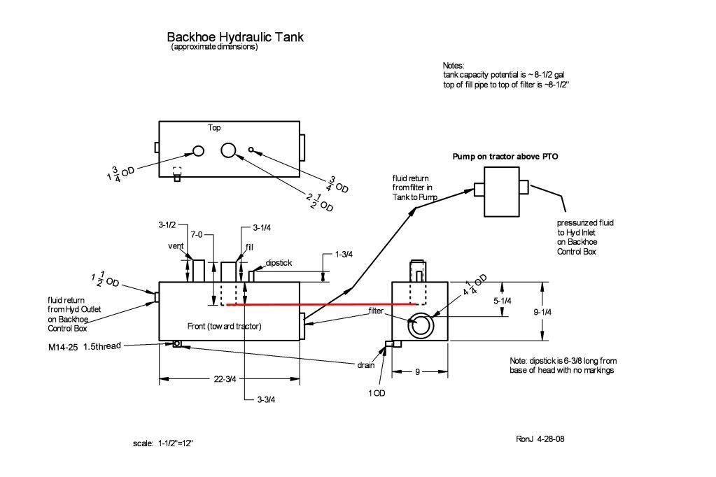
Here is a drawing of the tank on my JW03. You may want to check it against yours to see if we have the same tank.
RonJ

ronjin
Hymay,
How full are you keeping the hydraulic fluid in the tank?
The fluid return port from the valve is mounted pretty high on the tank.
RonJ
ronjin
I would not operate it that way for fear of blowing up the hydraulic pump. I would get a pressure gauge on it and see how much hydraulic pressure there is that causes the engine to stop.
RonJ
ronjin
Smokey,
I agree with Grumpy.
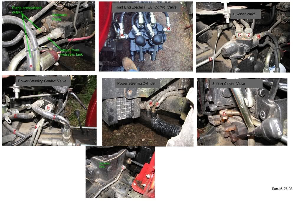
Just to be sure let us walk through the connections using the picture that I posted in #21.
Line A goes from the pump output in photo 1 to FEL valve input in photo 2. At point A in photo 2 is where your pressure gauge should be installed.
Line B represents your Power Beyond output from the FEL valve and should go to point B input in photo 3.
I would set it up so that the 3pt is fed from the Diverter valve as shown by D in photos 3 and 6. This will let the Diverter Valve do what was intended.
Finally, I would figure out how to get that remaining hose on the FEL valve (which is now simply a tank return hose since the Power Beyond is used) connected to Z shown in photos 3, 4, and 7.
RonJ
ronjin
Smokey,
Click on my icon at the upper left of this message. That will bring up my Profile. Send me your Email address and I will send you some information that may help to understand the functioning of a FEL control valve.
RonJ
ronjin
Smokey,
Thank you for the response. I will study this and get back to you this evening.
I download pictures this way:
Left-click on picture to open it up.
Right-click on picture should bring up a 'menu'.
Pick “Save Image As …” should bring up the 'save location' box.
I save it in my Pictures folder.
Then open the Pictures folder and Double-click on the file that you just saved.
That should open the file in whatever application your computer uses for JPEG images.
Go to the Edit menu to select the Print option.
RonJ
ronjin
Smokey,
I would like to help, but I am still waiting for a response to the questions that I asked back in note #21.
RonJ
ronjin

Smokey,
Here is a picture of my hydraulic hoses/flow. I know that it is not the same as yours, but perhaps we can use it for discussion.
The output hose (A) from your pump needs to feed the input port of the FEL control valve. That is where the Pressure Gauge should be attached.
Let's look at the FEL valve. Ignore the hoses that feed the FEL cylinders and you should have 2 hoses left. One is the input (for hose A) and the other ouput. Let's consider the hose out of that output as hose B. It needs to go into the input port of the Diverter Valve as shown in the 3rd picture. (While you are looking at the FEL valve, check to see if there are any “unused” ports that don't have hoses plugged into them. If there are, let us know.)
This should get us started talking.
Does your Diverter valve look like mine? You said that the FEL valve is presently fed out of the left side of the Diverter. Is that where mine shows line D? Where does your 3pt system get fluid from?
RonJ
ronjin
First, I would contact the people who replaced the hydraulic oil and find out what they really put in there. Sounds to me that they should have the responsibility to fix it. I would not run it until you know what they did.
RonJ
ronjin
Smoky,
1. Is your pressure gauge installed on the line that goes from the pump directly into the loader control valve?
2. If you can tell us what brand that loader control valve is – someone can probably tell whether and where the relief valve is on that valve. (or can you post a picture?)
RonJ
ronjin
-
AuthorPosts
